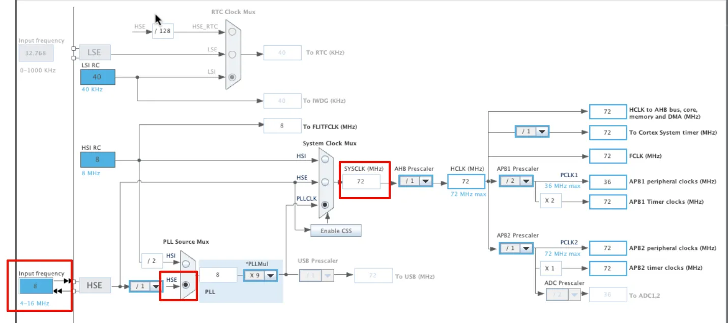
In this tutorial we will cover how to interface the SD Card with STM32 using the SPI protocol. The library used in this tutorial also supports the use of DMA for data transfer, increasing the SD card read and write speeds.
The library supports majority of the SD Card types, that includes SDSC (Standard Capacity), SDHC (High Capacity) and SDXC (eXtended Capacity).
Table of Contents
Introducing SD Card Module
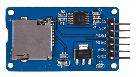
An SD Card SPI Module is a compact interface board used to connect an SD or microSD card to a microcontroller (like STM32 or Arduino) via the SPI (Serial Peripheral Interface) protocol. It provides level shifting and power regulation to safely operate the card at 3.3V, while allowing 5V-tolerant microcontrollers to communicate with it. The module enables easy reading and writing of data to SD cards, making it ideal for projects involving data logging, storage, or file handling.

Some of its features are:
| Feature | Details |
|---|---|
| SPI Interface Support | Communicates with microcontrollers using the standard SPI protocol. |
| Voltage Level Shifting | Includes built-in resistors or ICs to step down 5V signals to 3.3V. |
| Onboard Voltage Regulator | Converts 5V input from the microcontroller to 3.3V required by SD cards. |
| Standard SD & microSD Slot | Compatible with standard SD or microSD cards for flexible usage. |
WIRING DIAGRAM
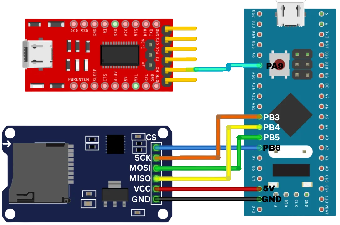
Below is the image showing the connection between SD Card Module and STM32F103C8. I have also connected a FT232 USB-to-UART converted with the MCU. This is to send the logs to the serial monitor using the UART.
As per the image, the connection is as follows:
| Peripheral | Peripheral Pin | STM32 Pin | Function |
|---|---|---|---|
| SD Card Module | CS | PB6 | Chip Select |
| SCK | PB3 | SPI Clock | |
| MOSI | PB5 | Master Out Slave In (Data to card) | |
| MISO | PB4 | Master In Slave Out (Data from card) | |
| VCC | 5V | Power Supply | |
| GND | GND | Ground | |
| FTDI Module | TX | PA9 | UART RX (to receive data on STM32) |
Note: Only the RX from FTDI is connected in this diagram, it’s used primarily for receiving data from the STM32.


